
Industrial Software
Industrial HVAC Inspection System
A newly developed Windows FCT station application for outdoor HVAC units, covering model identification, step-based inspection, multi-device communication, real-time judgement, and local result traceability.
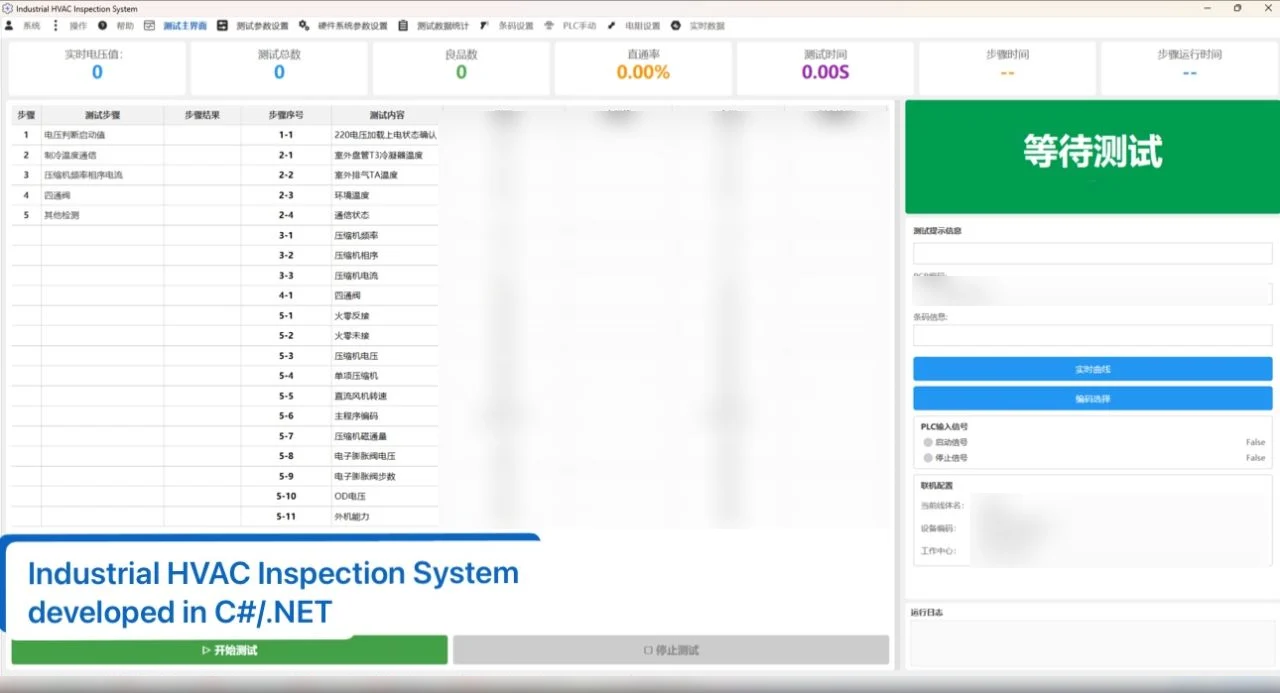
Project overview
This system is a Windows desktop application developed from the ground up for an outdoor HVAC unit FCT station. It brings model identification, inspection-plan loading, multi-device communication, step execution, real-time acquisition, rule-based judgement, and result recording into one reviewable workflow.
The delivered version is centered on the local station application. Customer identities, equipment models, production parameters, protocol details, and actual inspection data are excluded from this public case.
Operational context
An FCT station must run the appropriate sequence for each product model while coordinating PLC signals, barcode input, measurement modules, and communication with the unit under test. During a run, the application has to manage device state, step timing, live values, numeric or text-based rules, operator stops, and communication faults.
The software consolidates these tasks into one operator-facing system, from barcode input or manual model selection through inspection, judgement review, record lookup, and export.
My engineering scope
My scope covered:
- Requirement analysis and system-boundary definition
- Application architecture, WPF UI, and ViewModel development
- Configuration structures for models, inspection steps, and judgement rules
- PLC, barcode, measurement-device, and unit-controller integration
- Inspection state, step timing, judgement, timeout, and interruption logic
- SQLite result storage, historical queries, and Excel export
- Field commissioning, deployment, training, delivery, and maintenance
Inspection workflow
- Scan a barcode or select a product model manually.
- Load the inspection steps, judgement items, and runtime settings for that model.
- Initialize communication with the PLC, barcode device, measurement modules, and unit controller.
- Start the inspection from an operator command or PLC signal.
- Execute configured steps in sequence while continuously updating actual values.
- Evaluate numeric limits or text-based states according to the configured rules.
- Consolidate judgement items into step results and an overall inspection result.
- Save the overall record, step records, and judgement details to the local result database.
- Query records by date, barcode fragment, or result and export them to Excel when required.
System structure
- WPF presentation layer: Main inspection, configuration, history, live data, curves, and diagnostic views.
- Inspection workflow layer: Start, step transitions, timing, judgement, completion, failure stops, and operator interruption.
- Device adaptation layer: Unified management of PLC, barcode, measurement-module, and unit-controller state.
- Communication layer: Serial, TCP, UDP, and Modbus RTU communication used in the delivered system.
- Data layer: Separate management of configuration and runtime results, with SQLite used for inspection records.
Core engineering capabilities
- Model-specific inspection steps, durations, and judgement rules
- Barcode-to-model matching with manual model selection as an alternative
- Inspection start and stop through operator actions or PLC signals
- Background acquisition from multiple devices with unified runtime state
- Numeric-limit and text-state judgement
- Live data display and test trend curves
- Linked storage of overall, step, and judgement records
- Historical queries, summary statistics, and Excel export
- Handling for communication faults, timeouts, step failures, and manual stops
- Application and communication diagnostics
Device and communication integration
The delivered scope used Serial, TCP, UDP, Modbus RTU, and PLC integration. This public case describes the communication types and their engineering role without exposing ports, addresses, registers, equipment models, PLC points, or proprietary commands.
Barcode input, PLC control signals, measurement acquisition, and communication with the unit under test are normalized inside the application before being consumed by the inspection workflow and judgement logic.
Data and traceability
Each inspection creates an overall record, step records, and judgement details linked by an internal identifier. The history view supports filtering by time, barcode fragment, and result, reviewing step and judgement details, and exporting summary and detailed records to Excel.
Only the record structure and traceability workflow are described publicly. Real barcodes, measurements, limits, error logs, statistics, and database files remain private.
Reliability and exception handling
The system includes defined paths for disconnected communication, device read/write failures, invalid data, inspection timeouts, failed steps, operator stops, and PLC stop signals. Critical problems are reflected in application state or local logs so invalid data is not treated as a normal result.
MES extension boundary
The customer has requested a later extension that will upload inspection results to MES through HTTP POST for production traceability. This upload function is not part of the current delivered implementation. The existing local result structure provides a basis for the future interface, while payload fields, authentication, response validation, retry behaviour, offline buffering, and manual recovery still require definition and development.
Technology stack
- C# / .NET 8
- WPF / XAML
- MVVM-style separation of Views and ViewModels
- SQLite for local inspection results
- Local configuration database
- ClosedXML for Excel export
- Serial Port, TCP, and UDP
- Modbus RTU and PLC integration
Delivery status and public scope
The FCT station application has been delivered. This public case confirms the software structure, inspection workflow, communication types, data handling, and exception paths without claiming unverified accuracy, cycle-time improvements, deployment quantity, commercial outcomes, or MES production rollout.
Interface views
Additional project evidence to be added.
Inspection configuration
Reserved for the model, step, and judgement-rule configuration interface; demonstration parameters will be used before publication.
History and result export
Reserved for record queries, step details, and the Excel export workflow without real barcodes or production data.
Real-time data and curves
Reserved for the live measurement and trend interface; a test-environment capture will be added later.